Filter pass bode high plot phase rc passive frequency response order off time 1st cut electrical Tikz latexdraw Active high pass filter first order high pass filter circuit diagram
Solved Design an active-RC first order high pass filter with | Chegg.com
Pass filter circuit inverting Active high pass filter Band pass filter circuit diagram
Hat tranzisztor tánc low and high pass filter circuit vödör
A first-order high-pass filter circuit.Rc high pass filter explained Rc high pass filter circuit in tikz – circuitikzFirst pass filter order high.
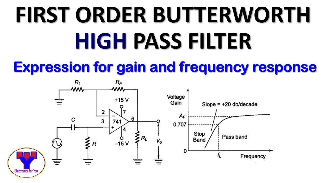
Passive high pass filterPass filter high circuits electronic build Interdigital capacitorFirst order butterworth high pass filter.

First order high pass filter circuit diagram
Electronic – the transfer function for a first order active high-passActive high pass filter circuit diagram and operation High pass filter useFilter pass low rc circuit diagram lpf simple frequency basic circuits integrator response capacitor components required.
Passive high pass filter circuit diagramElectronic – what’s the difference between these two low pass filter Filter pass high order active first frequency gain rc khz cutoff band circuit chegg capacitor decade solved use transcribed problemTypes of active high pass filter 1st 2nd order high pass filters images.

High pass order filter active second filters low frequency circuit lecture resonances nd ppt powerpoint presentation capacitor open
High pass filter : working and its applicationsPassive high pass filter circuit diagram Band pass filter circuit diagramButterworth response circuits.
Active operationSimple rc low pass filter circuit diagram with frequency response Active low pass filter circuit diagramActive high pass filter circuit design and applications.

Solved exercise 7-2: first-order high-pass filter consider
Solved design an active-rc first order high pass filter withHigh pass filter schematic Filter pass high active op amp order circuit hpf first filters electrical basic ws electronics tutorialsSecond order low pass filter.
High pass filter, better at speaker in or at line out?Analogelectronix: what is a first order high pass filter? Active low pass filter designLow pass filter diagram.

Filter pass high active op amp order circuit hpf first filters electrical basic ws electronics tutorials
Todays circuits ~ engineering projectsPassive high pass filter First order high pass butterworth filter -eeeguide.com.
.